- Home
- Knowledge library
- Fan ventilation in pig buildings (pressurisation)
Fan ventilation in pig buildings (pressurisation)
Use this information to understand how different air pressurisation systems provide ventilation in pig buildings.
In buildings that use air pressurisation, fans blow air into, or pressurise, the structure.
All the air enters the building at high velocity through the fan housing(s), therefore great care has to be taken to ensure this air does not create draughts.
Once this problem is overcome, pressurised systems are reliable because the entry of air can be controlled precisely. This is especially true in the case of ‘leaky’ buildings that use extraction systems, when holes or gaps in the structure act as air inlets and cause local draughts.
Ridge pressurisation with wall outlets
In ridge pressurisation systems, the fan(s) is mounted in the ridge and outlets are provided in the walls (see Figure 1).
This is a popular arrangement, which – with roof pitches of less than 15° – has the great advantage of not being susceptible to wind.
Provided the air outlets have back draught shutters, as the wind blows against one side, those on the windward side of the building close and those on the leeward open, exhausting the air.
In practice, the pressure differences are small between the ridge and the leeward wall, therefore wind-induced ventilation is minimised.
The main practical problem with any pressurised system s the distribution of incoming air from the fan(s). However, this distribution system offers some solutions to this.
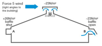
Figure 1. A ridge pressurisation system
Pressurised ceiling
An air-permeable material forms a false ceiling in the building to spread and reduce the velocity of the incoming air (Figure 2).
Fibre materials or sheet materials are used, with lots of small holes designed especially for this purpose.
The maximum air speed through a fibrous material should be no more than 0.15m/s (540m/h). This means that when sizing a system, 1.85m² of ceiling area is required for every 1,000m³ per hour of ventilating capacity.
To stop unwanted air leaking from the pressurised ‘loft’, all surfaces need to be sealed except for the porous ceiling.
The major disadvantage of the permeable ceiling is its tendency to clog with dust, which in time restricts air flow. Practical installations, therefore, require removable panels for easy cleaning.
A pressurised ceiling can be used in a variety of buildings, but is particularly suitable for those housing younger stock or where air speeds need to be low and even across the building. Where higher volumes of air are required, e.g. finisher pigs, opening inlets are incorporated into the ceiling.
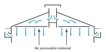
Figure 2. A pressurised ceiling
Baffled fan with air mixing facility
This involves a pressurising fan blowing down a short tube onto a horizontal air deflector, and out sideways through baffled guide vanes (Figure 3).
A recirculation fan can be positioned on the underside of the deflector. This draws up internal air from the house to the bottom side of the air deflector and exhausts sideways through the vanes. The incoming outside air and the recirculated air streams become mixed as they issue from the unit.
In winter, cold air can drop directly from the fan inlet causing cold draughts and this system overcomes this problem. The pressurising fan is speed-controlled to deliver enough air to maintain the required building temperature.
The recirculating fan can either be left to run continuously at full speed, or speed-controlled, increasing the speed as fresh air delivery is reduced, so that the slow-moving fresh air is entrained and mixed.
Application pressurised systems are useful in many new buildings and building conversions for pigs, except for very small rooms or buildings with solid pen divisions.
The key to success is air distribution: sufficient distribution points must be installed to give the required evenness of air flow.
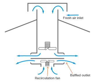
Figure 3. A baffled fan and air mixing facility
Recirculation systems
Recirculation systems use fans that run at higher speeds and draw up a proportion of recirculated building air to blend with the outside air. The amount of incoming air is regulated by a damper, which changes the ratio of recirculated to fresh air.
Recirculation systems can either be pressurising or depressurising and they are often supplied as factory-assembled units designed to be installed with minimum building alterations.
All recirculation systems have good pressure performance because the fans work at higher speeds when the building ventilation rate is low. As cold air is mixed with recirculated internal air, cold draughts are less of a problem.
Recirculation units must handle both cold air from outside and warm inside air for recirculation. Therefore, some proprietary systems are designed to draw in and exhaust air at the same point.
Such systems are inherently windproof because there is no wind pressure difference between inlets and outlets; ie, the system is perfectly balanced. They also offer the possibility of using exiting warm air to preheat the incoming cold air stream and can contain heat exchange coils for supplementary heating systems. This means that proprietary ventilation and heating systems can simply be 'plugged in' to the side of a building.
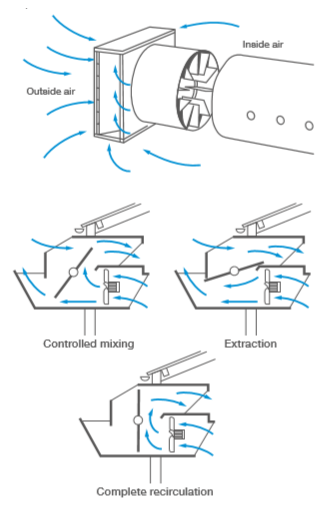
Figure 4. Recirculation systems
Down jet systems
These systems involve the introduction of air into a building through long, narrow slots, or ‘down jets’, at the sides of the building.
The slots are 50 mm wide to allow a maximum air speed of 4–5m/s. The two main design layouts are shown in Figure 5.
In general, the system offers a simple way to provide, under all external weather conditions, a defined lower temperature dunging area towards the side walls of the building without the use of complicated inlet modulating devices (as used in the high-speed jet system).
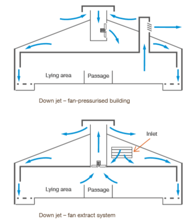
Figure 5. Down jet ventilation systems
Topics:
Sectors:
Tags:

